Description

This project does not have a descriptive photograph.
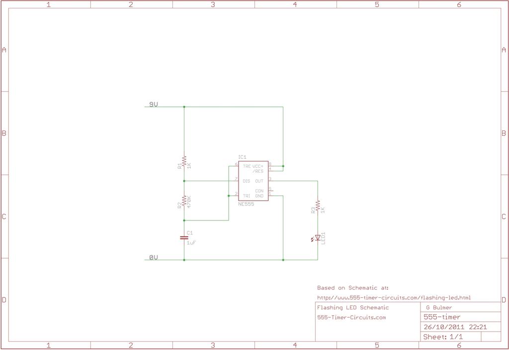
This circuit uses the 555 timer in an astable operating mode generating a continuous output via pin 3 in the form of a square wave. This turns the LED on and off at a speed set by the values of R1 and R2.
Schematic
Board
This project does not have a board layout.
Bill of Materials
| Designator | Value | Description |
|---|---|---|
| C1 | 1uF | Capacitor |
| IC1 | NE555 | General purpose bipolar Timer |
| LED1 | LEDs | |
| R1 | 1K | Resistor |
| R2 | 470K | Resistor |
| R3 | 1K | Resistor |
[JSON]
This project is published under the terms of the Creative Commons Attribution-ShareAlike 3.0 Unported licence.